
Making your own cables is easy -- uhh, well, uhmm not that hard. First, let’s get some of the basics covered.
To make cables you need to have CAT5 wire. Better yet get CAT5 enhanced cable so you can take advantage of NICs (Network Interface Cards) of the future. Don’t even think about CAT6 – there is no interchangeable standard and it is only as fast as using all 4 pairs of your CAT5 wire (if there was a NIC that supported it).
Just who are you calling twisted?CAT5 wire is telephone wire, so we get to learn a bit about telephone cables. Good telephone IW (Internal Wiring) uses real telephone cables with twisted-pairs of wire or two wires that slowly wrap around each other. Twisted pairs are used because both wires are pretty much exposed to the same magnetic field as they revolve each other so that any electro magnetic interference cancels out.
If we used two parallel wires to connect a phone circuit it would pick up so much 60-cycle hum as to be close to unusable. (You might have experienced this by using silver-satin, the common cable used to connect a phone to the wall outlet. These wires run parallel and will pick up hum if run for any distance over 6 feet.
Secret tip: Many houses have phones wired using non-twisted pairs which will reduce your MODEM connect speed! Replacing the wire from your service entrance with real twisted-pair phone wire will help you get those faster connect speeds with a 56K MODEM.) Likewise, 10/100Base-T wiring also won’t work unless you have twisted pairs.
Back to CAT5 telephone cable. Phone circuits have two wires – tip and ring. (These terms refer to the old phone plugs that point was called the tip and the hole of the jack it plugged into formed the ring). The twisted pairs have color codes where one wire is of a color X (primary color) with a color Y (secondary color) stripe, and the other wire is color Y with a color X stripe. The first pair in a phone cable is White/blue (white with a blue stripe) or tip and Blue/White (that is blue with a white stripe) or ring.
| Pair number | Group number | Primary Color | Secondary color |
|---|---|---|---|
| (if mostly this color it is the tip) next is the RJ21X pin number | (if mostly this color it is the ring) next is the RJ21X pin number | ||
| 1 | 1 | White 26 | Blue 1 |
| 2 | 1 | White 27 | Orange 2 |
| 3 | 1 | White 28 | Green 3 |
| 4 | 1 | White 29 | Brown 4 |
| 5 | 1 | White 30 | Slate 5 |
| 6 | 2 | Red 31 | Blue 6 |
| 7 | 2 | Red 32 | Orange 7 |
| 8 | 2 | Red 33 | Green 8 |
| 9 | 2 | Red 34 | Brown 9 |
| 10 | 2 | Red 35 | Slate 10 |
| 11 | 3 | Black 36 | Blue 11 |
| 12 | 3 | Black 37 | Orange 12 |
| 13 | 3 | Black 38 | Green 13 |
| 14 | 3 | Black 39 | Brown 14 |
| 15 | 3 | Black 40 | Slate 15 |
| 16 | 4 | Yellow 41 | Blue 16 |
| 17 | 4 | Yellow 42 | Orange 17 |
| 18 | 4 | Yellow 43 | Green 18 |
| 19 | 4 | Yellow 44 | Brown 19 |
| 20 | 4 | Yellow 45 | Slate 20 |
| 21 | 5 | Violet 46 | Blue 21 |
| 22 | 5 | Violet 47 | Orange 22 |
| 23 | 5 | Violet 48 | Green 23 |
| 24 | 5 | Violet 49 | Brown 24 |
| 25 | 5 | Violet 50 | Slate 25 |
White with blue can be listed as WH/BL and blue with white becomes BL/WH. Thus pair one is made up of WH/BL and BL/WH.
For 25+ pair cable there are more than one of every color combination. To keep them straight, the first 25 pairs are bundled together with a WH/BL yarn or plastic string wrapped around them. The next 25 pairs have a white/orange and so on until we get to 25 bundles of 25 pairs (a total of 625 pairs). Going to the next level, there are super bundles, made of 25 bundles with a white/blue string around it – this could go on to 25 super bundles of 25 bundles of 25 pairs or 15,625 pairs! You won’t see any real cables with more than 3600 pairs. The pairs are twisted and the group of pairs also twists in a slight clockwise rotation. (often you will see TELCO cables terminated at 66-blocks or 110 blocks)

What is interesting is that pair-one is in the middle. This is not used for data in the current setup and is sometimes used for voice. Pair 4 is also not used and is sometimes used for power to a to a telephone set.
| Straight-through Cable – both ends | ||||||||
|---|---|---|---|---|---|---|---|---|
| Pin# | 1 | 2 | 3 | 4 | 5 | 6 | 7 | 8 |
| Wire color | WH/OR | OR/WH | WH/GR | BL/WH | WH/BL | GR/WH | WH/BR | BR/WH |
| Pair | 2 tip | 2 ring | 3 tip | 1 ring | 1 tip | 3 ring | 4 tip | 4 ring |
Strip the end of the cable sheath off and separate the pairs. Now take a twist or so out of the pairs being sure not to confuse the whites; some cables don’t put any stripes on the white or have a long distance between the stripes. Straighten the curl out of the wires and put them in order as the chart above. Trim the ends so they stick out of the cable about ½”. Check to make sure that the wires are still in the correct order and slide them into the connector.
Now, check and make sure that ALL the wires are all the way down to the very end of the connector (look from the end). Check once more that the wires are in the correct order and crimp. Check one last time to make sure the wires are all the way to the end of the connector and in the correct order.
Crimp with a professional crimping tool, such as AMP’s 2-231652-0. This tool has interchangeable heads for crimping RJ-45, RJ-11 and RJ-41. Don’t try to use a cheap tool – it might cause intermittent problems that will cost you much more in time that the right tool costs.
Before plugging the system together it is a good idea to test the cables with a tester such as line test 1 or 2 – I recommend Line test 2 – it is the easiest to use and has saved me a lot of time..
Cable length should not exceed 100 meters (328 feet). This distance can be extended with a repeater or hub in the middle.
There is also a crossed cable, for connecting two computers together without a hub, or hubs that don't have the extra jack. Pairs 2 and three are exchanged at one end.
For one end use the table above but for the other use the following table table.
| Crossed Cable – Second End Only | ||||||||
|---|---|---|---|---|---|---|---|---|
| Pin# | 1 | 2 | 3 | 4 | 5 | 6 | 7 | 8 |
| Wire color | WH/GR | GR/WH | WH/OR | BL/WH | WH/BL | OR/WH | WH/BR | BR/WH |
| Pair | 3 tip | 3 ring | 2 tip | 1 ring | 1 tip | 2 ring | 4 tip | 4 ring |

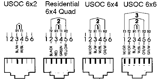
Telephone jacks have this familiar, yet poorly understood nomenclature. AMP, who sells most of theses connectors, has failed to include the RJ numbers as reference in their catalog. Because they don't have a clue as to how to organize their products , I've added the common part numbers below.

| Pin number | 1 | 2 | 3 | 4 | 5 | 6 |
|---|---|---|---|---|---|---|
| NC | NC | R1 | T1 | NC | NC |
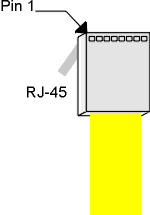
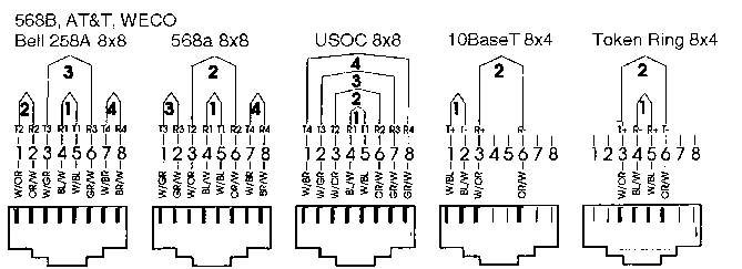
Think of the pictures below as if you are looking at the phone jack in the wall. That is you are looking into the opening of the Jack as if you are ready to put the plug in.

| Pin number | 1 | 2 | 3 | 4 | 5 | 6 |
|---|---|---|---|---|---|---|
| NC | A | R1 | T1 | A1 | NC |
When a phone goes off hook, the tip/ring loop closes and the A/A1 circuit closes, both through the hook switch contacts. When the telephone user wishes to put the call on hold, he pushes the 'hold' button which OPENS the A/A1 circuit. In other words, 'hold' intention is signaled by opening the A/A1 circuit while there is tip/ring loop current present. Then as the caller releases the 'hold' button, it pops up the line button. The tip/ring loop is now open, but the call is held by the KSU. When the call is picked up from hold, tip and ring are re-established, and the A/A1 circuit is closed, which actually releases the hold. Timing is critical. If the A/A1 hook-switch contacts open BEFORE the tip/ring contacts, the call will go on hold when the receiver is hung up. This is why you will find that the A/A1 contacts always establish before the tip/ring on both the hook-switch and on the line keys.
| Pin number | 1 | 2 | 3 | 4 | 5 | 6 |
|---|---|---|---|---|---|---|
| NC | T2 | R1 | T1 | R2 | NC |
| Pin number | 1 | 2 | 3 |
|---|---|---|---|
| R1 | NC | T1 |
| Pin number | 1 | 2 | 3 | 4 | 5 | 6 |
|---|---|---|---|---|---|---|
| MB | NC | R1 | T1 | NC | MB! |
| Pin number | 1 | 2 | 3 | 4 | 5 | 6 |
|---|---|---|---|---|---|---|
| MB | A | R1 | T1 | A1 | MB! |
| Pin number | 1 | 2 | 3 | 4 | 5 | 6 |
|---|---|---|---|---|---|---|
| R3 | T2 | R1 | T1 | R2 | T3 |
| RJ26X | ||||||
|---|---|---|---|---|---|---|
| FLL Fixed Loss loop | to programming resistor | Out | ||||
| line | T | R | T (PR) | R (PC) | T | R |
| 1 | 26 | 1 | 28 | 3 | 27 | 2 |
| .. | .. | .. | ... | ... | ... | |
| 8 | 27 | 22 | 49 | 24 | 48 | 23 |
| Pin number | 1 | 2 | 3 | 4 | 5 | 6 | 7 | 8 |
|---|---|---|---|---|---|---|---|---|
| T2 | NC | NC | T1 | R1 | NC | NC | R2 |
| Pin number | 1 | 2 | 3 | 4 | 5 | 6 | 7 | 8 |
|---|---|---|---|---|---|---|---|---|
| T2 | A | NC | T1 | R1 | NC | A1 | R2 |

RJ41S for use with RJ25X - some ATT modems AMP5-554739-3 plug 555166-1 jack
| Pin number | 1 | 2 | 3 | 4 | 5 | 6 | 7 | 8 |
|---|---|---|---|---|---|---|---|---|
| R(FLL) | T (FLL) | MI | R(P) | T(P) | MIC | PR | PC |
| Pin number | 1 | 2 | 3 | 4 | 5 | 6 | 7 | 8 |
|---|---|---|---|---|---|---|---|---|
| NC | NC | MI | R(P) | T(P) | MIC | PR | PC |
| Pin number | 1 | 2 | 3 | 4 | 5 | 6 | 7 | 8 |
|---|---|---|---|---|---|---|---|---|
| NC | NC | T2 | R1 | T1 | R2 | NC | NC |
RJ48 An 8-position jack wired with four conductors on 1/2/4/5, often used for T-1 networking connections.
| Pin number | 1 | 2 | 3 | 4 | 5 | 6 | 7 | 8 |
|---|---|---|---|---|---|---|---|---|
| T2 | R2 | NC | R1 | T1 | NC | NC | NC |
RJ48S An 8-position keyed jack wired with four conductors on 1/2/7/8, often used for T-1.
| Pin number | 1 | 2 | 3 | 4 | 5 | 6 | 7 | 8 |
|---|---|---|---|---|---|---|---|---|
| T2 | R2 | NC | NC | NC | NC | T4 | R4 |
RJ48X: An 8-position jack wired with four conductors on 1/2/4/5, with a shorting bar that allows a signal to pass from one pair to the other when a plug is not inserted in the jack.
RJ61X: An 8-position jack wired with all eight conductors. RJ61X is in actuality what is commonly referred to as an RJ45 today. See EIA/TIA 568B below
| Straight-through Cable – both ends | ||||||||
|---|---|---|---|---|---|---|---|---|
| Pin# | 1 | 2 | 3 | 4 | 5 | 6 | 7 | 8 |
| Wire color | WH/OR | OR/WH | WH/GR | BL/WH | WH/BL | GR/WH | WH/BR | BR/WH |
| Pair | T2 | R2 | T3 | R1 | T1 | R3 | T4 | R4 |
Sometimes called T568A. A common arrangement for networking that uses an 8-position jack wired with all eight conductors, standardized by the Electronics Industry Association and Telecommunications Industry Association. Pairs 1 and 2 are on pins 4/5 and 3/6, respectively, and as such allow for backwards-compatibility with older USOC jacks. However, as pairs 3 and 4 are on pins 1/2 and 7/8, respectively, the entire jack is not USOC-compatible. It is sometimes used for 10-Base-T wiring, but is more suited for Type-3 Token Ring.
Also called T568B and by AT&T's 258A spec. The most common wiring scheme for 10-Base-T and 100-Base-T networking today. It specifies an 8-position jack with all eight conductors wired; however pairs 1 through 4 are on pins 4/5, 1/2, 3/6, and 7/8, respectively. The only difference between T568B and T568A is the arrangement of wire pairs. A patch cable of either type will work on the other (wire pairs will simply be different colors). Be cautioned, however, that jacks wired for one type will not be compatible with equipment wired for the other.
Just a T568B pattern with the unnecessary pairs removed, leaving only pairs 1/ and 3/6 wired.
Digital Equipment Co.'s proprietary Modified Modular Jack. It is identical to a standard USOC 6-position jack, except that the locking tab has been offset to the right to prevent an MMP (modified modular plug) from fitting into a USOC jack. AMP5-555237-2 Plug
Realize that there are three connectors housings. (four if you count DECs)
| USOC type | Positions | Contacts | AMP Plug# | AMP Jack # | *AMP Die # |
|---|---|---|---|---|---|
| RJ22 | 4 | 4 | 5-641334-3 | 520249-2 | 853400-3 |
| RJ11 | 6 | 4 | 5-641335-3 | 555163-2 | 853400-8 |
| 6 | 6 | 5-641337-3 | 555163-1 | 853400-8 | |
| DEC RJ11 offset | 6 | 6 | 5-555237-2 | 555003-1 | 853400-6 |
| RJ45 | 10 | 8 | 5-554739-3 | 555162-1 | 853400-7 |
| 10 | 10 | 5-557963-3 | 558065-1 | 58560-2* |
*The 10 position uses 58560-2 +59980-1 (Big Bucks!@#$)
All other dies use the 2-231652-0 crimper
RS232 DB9 pinout and null modem wiring.
If you found this information useful - all I ask is to look at our home page and see if we have any products that might be of use to you or a colleague. Link to us if you can.
 | 3209 W.9th street | Ph | (785) 841 3089 (785) 841 0434 mailto:inform@xtronics.com?subject=10/100BaseT http://xtronics.com/index.htm | Bookmark this page |
| Transtronics Home Page See our line of industrial control electronics | PLC's Index | PC test equipment and EPROM programmer | Process Control Panel meters | Current sensors | Resource library handbooks, primers and spec sheets |
Corporate information and privacy statement
(C) Copyright 1994-2006, Transtronics, Inc. All rights reserved
Transtronics® is a registered trademark of Transtronics, Inc.